
High-Performance Quad Headphone Buffer
Sep 06, 2019
Typical portable devices such as smartphones and personal audio players are designed to drive headphone impedances of 16 ohm or higher at the 1Vpeak level.
Many higher quality iem (in ear monitors) earbuds have impedances as low as 10 ohm. External headphone amplifiers can improve the quality of the headphone audio
output by providing a high-impedance load > 1kohm and thereby buffering (isolating) the player's output. The circuit described here is a high-performance rudimentary external headphone buffer/driver.
Each audio channel consists of two dual op-amps (or a quad of individual circuits) to increase current output from 25 mA to 100 mA.
The schematic diagram below shows the configuration for one dual op-amp:

The assembled prototype is shown below. The layout allows for convenient substitution of different op-amps and easily adding output load resistance for RMAA testing purporse:
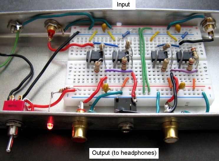

Each channel of this high-performance headphone unity-gain buffer circuit consists of 2 dual-opamps (4 opamp circuits) stacked in parallel. The LM4562NA opamp duals can
source ~ 25 mA per circuit without clipping so each channel can deliver up to 100 mA of load current, shared equally between each circuit. Other high-performance audio op-amps designed to operate
properly at supply voltages down to +/- 2.5VDC can be substituted. For example a 10 ohm headphone load can be driven with a maximum
input signal level of 1.0Vpeak without clipping. A typical measured Samsung Galaxy S4 peak output level (15/15 on level slider) is 0.80Vpeak.
Using a low supply voltage ensures that the thermal dissipation limits of the opamps won't be exceeded. Since each circuit of the dual opamp has a quiescent current
draw of 5 mA, the entire quad circuit will draw (zero signal) 40 mA current.
For the input signal voltage ranges of interest, the circuit can be easily powered with a +/- 3VDC pack (4 AA) alkaline batteries or 4 AA rechargeable NiMH batteries.
Under typical listening conditions 25 - 35 hours of listening time can be expected. For headphone impedances greater than 20 ohm, each channel can be powered
with a single dual op-amp with the same audio performance. In this case, the battery power consumption will roughly halved and over 50 hours of listening can be
expected with 2200 mA.Hr rechargeable batteries. The chart below shows the typical battery voltage voltage discharge (for 2 AA rechargeables) with a 100 mV average level of
applied signal. The LM4562 opamp is specified to operate with power supplies as low as +/- 2.5V supplies:

Audio Performance
The quadbuffer circuit has very low noise properties. In a noise bandwidth of 20 kHz, the total output voltage noise with open input is 2.0 uVrms, dominated mainly by the
thermal noise of 3.3kohm input resistance. However, since the circuit
is intended to be used with low input loads such as low impedance headphone output circuits, this will reduce the input thermal noise contribution. For input loads < 100 ohm (or shorted), the total output voltage noise is
~ 0.25 uVrms and is dominated by the op-amp en voltage noise. For a maximum signal level of 1Vpeak (or 0.71Vrms), this translates to a S/N ~ 129 dB. Paralleling of four op-amp circuits in the quadbuffer configuration reduces
the op-amp voltage noise contribution at the output by about half (6dB improvement) compared to a single op-amp.
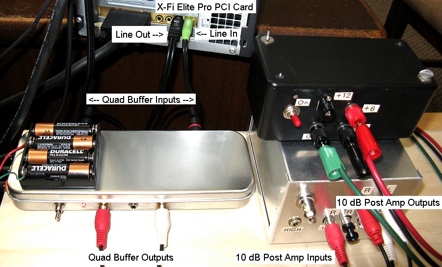
The fairly standard RMAA test setup is shown below. The main line-out of a Creative X-Fi Elite Pro sound card was connected to the QuadBuffer circuit. The output of the QuadBuffer was connected to a
10 dB linear very low noise post amplifier to boost the signal amplitude to the nominal level recommended for RMAA test purposes (approximately 2.95Vpeak for this sound card).
The output of the post amplifier was connected to the line-in of the X-Fi Elite Pro sound card. Battery power supplies were used to minimize noise:
Detailed RMAA measurements for a 10 ohm load case demonstrate excellent audio characteristics.
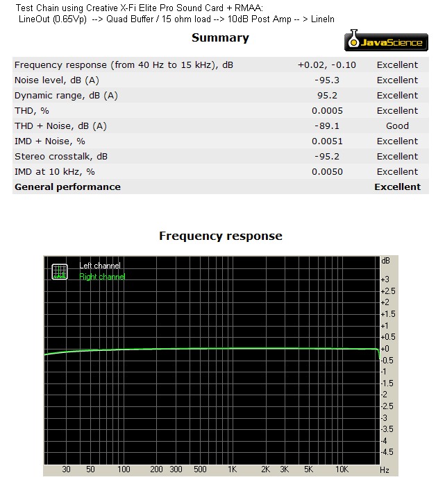
The RMAA summary results shown below are for a resistive load of 15 ohm on each channel, simulating fairly low-impedance headphones. The test signal amplitude
driving the quad buffer input corresponds to a Samsung Galaxy S4 audio output level of ~ 14/15:
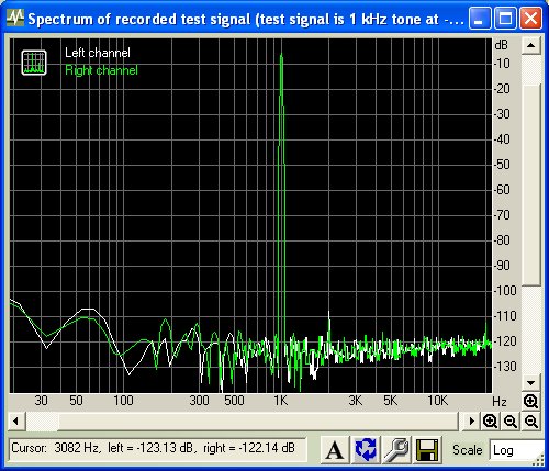
The very low distortion of this buffer circuit, even for significant current output drive is clearly seen in the 1 kHz spectrum below:
An extended Bode plot is shown below, with 15 ohm loads and with 1Vpeak input signal showing a flat response from 1 Hz to over 1 MHz:

Thermal Considerations
It is always important to consider the thermal dissipation of the op-amps, particularly when driving low impedance loads. Using the lowest possible power-supply
voltage consistent with the required output voltage helps to lower the op-amp thermal dissipation and reduces battery drain.
As an example, consider the case of a 10 ohm output load with an input voltage of 1Vpeak. For a 10 ohm load, this is the maximum possible output voltage before current limit.
Consider one audio channel which consists of 2 quad op-amps (or 4 op-amp circuits) driving the same 10 ohm output load resistor in parallel (the 2 ohm current balancing resistors in each channel
will be ignored here as they don't change the result significantly).
For thermal calculation purposes, this is equivalent to each individual op-amp circuit driving a peak current of 25 mA into a 40 ohm load. Under these conditions,
assuming the op-amps have a typical push-pull final drive stage, the power dissipation of each op-amp circuit is 35mWrms or 70mWrms for both
circuits in one dual op-amp package. This is the power dissipation associated with the output signal swing. This is only part of the package dissipation. To this must be added the
DC quiescent (no signal applied) power dissipation. The quiescent current draw of each op-amp circuit in the dual package is ~ 5 mA. Therefore the quiescent
power dissipation for a dual op-amp, considering we have +/- 3V supplies is 6V*2*5ma = 60 mWrms. Therefore the total dual-package power dissipation under these conditions is
130 mWrms. The thermal resistance of a typical DIP package is ~ 100 deg/watt. The resultant temperature INCREASE above ambient temperature of the dip package under these
conditions is therefore ~ 13 deg. Hence the DIP package will operate well within its operating thermal range (typically Tcmax ~ 110C under typical ambient conditions, allowing for reasonable margins).
The power delivered to the single 10 ohm load for each stereo channel is 1.0/2/10 = 50 mWrms.
Therefore the total power draw from a +/- 3VDC supply for both stereo channels or 4 LM4562NA quad op-amps driven with an input signal voltage of 1Vpeak into 10 ohm loads is:
Psupply = 4*(130) + 2*50 = 620 mW . Therefore since the total power delivered to the 10 ohm loads is 100 mW, the output efficiency is ~ 16%.
Direct measurements on the circuit above with the conditions of +/-3VDC supplies, 10 ohm loads on each stereo channel and 1Vpeak input signal show Iq = 35 mA (total of all op-amps).
At 1Vpeak signal, the total supply current was measured to be 86mA corresponding to a total supplied power of 516 mW in reasonable agreement with the calculation above and confirming that the op-amps
are running "cool" as confirmed by a finger test after several minutes of operation with applied signal.
What happens if the output is short circuited? Each of the individual op-amp circuits (4 per channel) has a 2 ohm series resistor which is the effective load seen by each circuit in this case.
Assuming again a maximum input signal voltage of 1Vpeak, the op-amps will operate in current limit mode delivering ~ 25 mA peak current and the peak output (clipped) voltage across each 2 ohm
resistor will therefore be 50mV. Assume the clipping creates a square-wave output voltage, the worst-case scenario for power-dissipation. The power dissipation for each dual op-amp package
due to this signal, for the assumed 3VDC supplies is is easily calculated to be ~ 150 mW. Adding the same quiescent dissipation as above of 60 mW, we calculate 210 mW of total dual-package
power dissipation for this short-circuit condition. This corresponds to a temperature rise of 21 deg which again is well within the thermal capabilities of this op-amp for normal ambient conditions.