1 MHz Wien-Bridge Oscillator
M. Gallant Feb. 04, 2008
The classic Wien-Bridge oscillator, with incandescent lamp nonlinear stabilization, provides a low
distortion sine wave source. A thorough and clear discussion of the Wien-Bridge oscillator is
provided in Malvino's Electronic Principles. Using an inexpensive opamp with sufficient bandwidth and slew-rate, it is possible
to nudge the oscillation frequency of this classic circuit into the MHz range. The following simple circuit
demonstrates a 1.27 MHz Wien-Bridge oscillator.
Although intended for use in ultra low noise/distortion premium audio applications, the
National LM4562 opamp
has sufficient bandwidth, slew rate (GBW: 55 MHz, SLR: 20 V/us) and output drive capability to
provide decent MHz signal oscillation. At 1 MHz, in order to stay within the slew-rate limit, the
circuit must be designed with an oscillation amplitude of less than 2Vp. This can be achieved
by proper selection of the incandescent lamp and feedback resistor. At the oscillation frequency,
determined by the lead-lag network feedback transmission peak, the lamp resistance must be exactly
half the feedback resistance. The lamp resistance, which increases with voltage, is determined by the RMS voltage across the lamp, so
the voltage feedback network must satisfy this condition. (As a guideline, it is useful to measure
the DC resistance versus voltage of the lamp). Also the values must be within the current drive capability of
the selected opamp. In addition, the output signal peak amplitude must be within the voltage range
capability for the available Vcc/Vee supply. Fortunately, these conditions are easily satisfied with
a little planning.
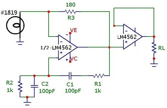
The Wien-Bridge lead/lag network component values in this design are 100 pF and 1kohm (which theoretically provide
oscillation at 1.59 MHz).

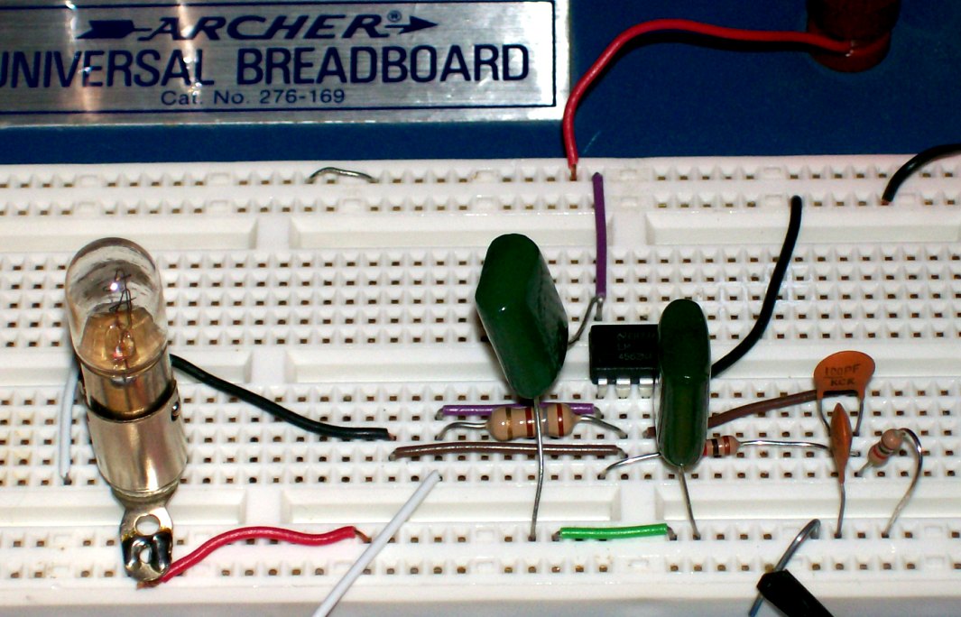
In this example a #1819 lamp, nominally 28 V @ 40 mA was used. Using
standard resistor values, an Rf of 180 ohm provides output oscillation at 1.27 MHz with 1.35 Vp amplitude,
within the slew-rate limit. With a supply voltage of +_3.0V, the LM4562 can operate within 0.5V of the rails, and so the circuit can
be conveniently powered using 4-AA cells as a split supply. The protoboard layout and overall
test configuration are shown below (in this case powered by a split 8-AA supply although it does function
identically with +_3.0 V supply).
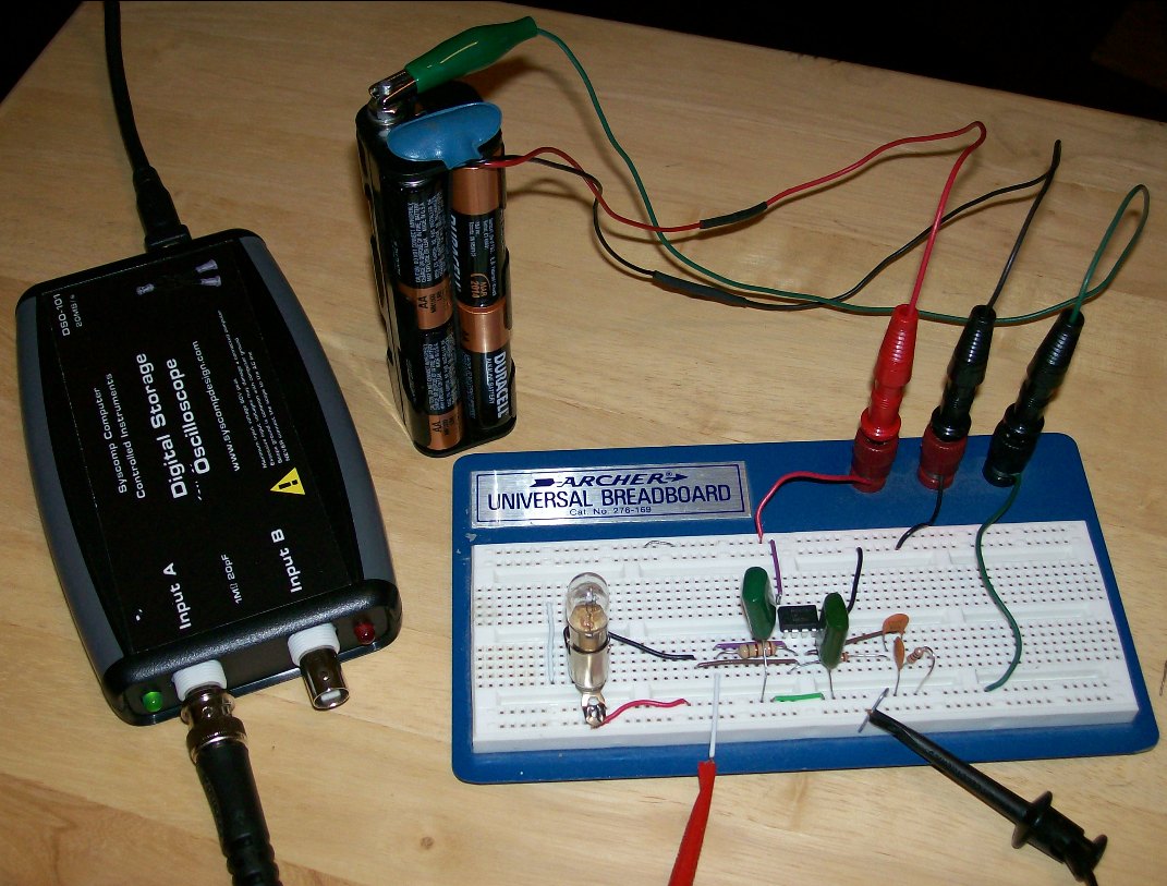
The circuit oscillates at 1.27 MHz as shown below, and is quite stable even at this relatively high frequency.
The discrepancy in frequency is due to non-ideal opamp effects (discussed below) which shift the oscillation condition from
the ideal zero-degree phase shift point of the lead-lag network and thus pulling the oscillation frequency to lower values.
Since the negative feedback loop resistance is rather low, the drive capability
of the opamp and output resistance will also shift the operating point. Use of lamps with higher
resistance values (e.g. #80, 327, 344, 1869, 2158, 7218 lamps) will provide greater feedback resistance and less current consumption,
although in the present circuit, the output signal current draw is low by design at about 5 mA, well within the drive capability
of the opamp.

The LM4562 is a dual opamp so the Wien-Bridge can be easily coupled to a unity-gain buffer. In this configuration, a rock solid 1.27 MHz
test signal circuit can be implemented. The circuit below was tested under different loads RL, and the output amplitude
and frequency were constant (Vout=1.35 +-0.01 Vp, f= 1.27 +_0.005 MHz) down to loads as low as and including 50 ohm (at which point the
output current draw is Ip = 27 mA .. roughly the limit of this opamp). Futhermore, this opamp can drive
capacitative loads as high as 100 pF. With a 50 ohm resistive load AND a 3 ft. RG-58U test cable terminated into a 1 Mohm scope input (about 100 pF
shunt capacitance), the 1.27 MHz was unchanged.
The circuit can obviously be used, with change of lead/lag network values, to generate extremely low
distortion test audio signals in the 100 Hz to 20 kHz audio range as well as ultrasonic signals in the
hundreds of kHz range. It would be interesting to make careful
measurements of sine signal purity in the ultrasonic range, considering that this opamp is specified
with such low distortion and offset parameters.
Discussion of Oscillation Frequency
As noted above the circuit oscillates at 1.27 MHz. With an ideal opamp and neglibible parasitics, using the component values an
oscillation frequency of 1.59 MHz is expected. If we allow a reasonable layout capacitance of about 10 pf for each of the
Wien feedback capacitors, the predicted oscillation frequency drops to about 1.45 MHz, still well above the measured frequency.
The finite gain of the opamp alone can account for the oscillation frequency as follows:
If we assume an ideal opamp EXCEPT for the finite gain-bandwidth product, (i.e. ignoring opamp input resistance,
output resistance and other real opamp limitations) then with Aol(f) being the frequency dependent open-loop gain, the input error
ac voltage creates an output ac voltage (in the oscillation state):
   Vout = Aol(f)(v+ - v-)
 where
   Aol(f) = Amid/(1 + j*f/f2)

 (Amid = 1E7 and f2 = 5 Hz for LM4562)
and the inverting and noninverting input voltages, as determined by the respective feedback fractions are:
   v- = Vout*Zin/(Zin + Zfn)
and
   v+ = Vout*Zip/(Zip + Zfp)
where Zin, Zfn are the inverting input and feedback complex impedances respectively and
where Zip, Zfp are the noninverting input and feedback complex impedances as shown below:
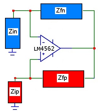
In the basic Wien-Bridge circuit here, Zfn = R3 and Zin = lamp-resistance (with Zin=R3/2 being the oscillation condition with an ideal opamp).
Zip is R2 || C2 and Zfp is R1 in series with C1. In the Wien circuit R2 = R1 and C2=C1.
Substitution leads to the complex oscillation condition:
  1 = Aol(f)*{Zip/(Zip + Zfp)  -  Zin/(Zin + Zfn)}

and since  f>>f2,

  Aol(f) ~ Amid*f2/(j*f)  = GBW/(j*f)

or:
   Zip/(Zip+Zfp) =  Zin/(Zin+Zfn) + j*f/GBW
Note that the ideal opamp condition, with GBW --> infinity, is the familiar Wien-Bridge balancing condition. However, opamps with finite gain-bandwidth
will shift the oscillation condition to SHORTER frequency (positive phase shift) as determined by the imaginary term j*f/GBW. To determine the
exact frequency, the equation can be easily solved numerically using various techniques. The lamp-resistance Zin and frequency are varied to satisfy the
equation, by equating real and imaginary parts. The nonlinear negative resistance of the lamp (or other nonlinear feedback approaches)
will ensure that the system will stabilize to this oscillation condition.
For the present circuit (with Rfn = 180 ohm, C1=C2= 110 pF and R1=R2= 1kohm), the oscillation condition is satisfied for Rlamp = 89 ohm (just 1 ohm from
the ideal perfect opamp condition) and f = 1.28 MHz ... almost exactly the measured value of 1.27 MHz. Because the amplifier still has significant open-loop gain at the
oscillation frequency, the error voltage is small enough that the bridge-balance is still close to the ideal case, and the lamp resistance required (and hence RMS
AC voltage level) is nearly equal to the ideal case.
Compared to the ideal Wien-Bridge circuit, where the lead-lag network oscillation point is at the peak point (0.3333 value) and at zero phase, using a
finite 50 MHz GBW opamp here causes the oscillation condition to be shifted slightly but measureable to ~ 4.8 deg. below the ideal point.
The oscillation condition is of course still very close to the peak of the lead-lag transmission curve (shifted very slightly down to about 0.3321).
Because the negative feedback fraction and oscillation location are very close to the peak, we can get a simplified
first approximation for the phase shift and oscillation frequency using the ideal values on the RHS of the expression:
Phase(Zip/(Zip+Zfp)) = ATAN{ (Zin + Zfn)/Zin*f/GBW }
which predicts a 5.1 deg. phase shift and a frequency of 1.27 MHz, within a few percent of the exact calculated value.
The following Wien lead-lag network transmission curves (upper is magnitude, lower is phase) shows the ideal point and the
actual oscillation point for the current circuit components:
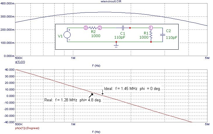
The oscillation frequency will be closer to the Wien-Bridge ideal case at lower frequencies, where the f/BGW correction will be negligible.
References
- "Electronic Principles", A. Malvino, 3rd Edn. McGraw Hill, 1984, p 610
- "IC OP-AMP Cookbook", W. Jung, 2nd Edn. SAMS, 1983, p 360