
AR Coating Calculator
Nov 24, 2014
 This note discusses the single-layer antireflection (AR) coating for arbitrary angles of incidence. The incident medium N1 and the AR coating layer N2 are
assumed lossless. The substrate medium N3 may be lossy. Synthesis calculators are provided for computing the AR coating layer index N2 and thickness T2 and
the formal mathematics is included.
This note discusses the single-layer antireflection (AR) coating for arbitrary angles of incidence. The incident medium N1 and the AR coating layer N2 are
assumed lossless. The substrate medium N3 may be lossy. Synthesis calculators are provided for computing the AR coating layer index N2 and thickness T2 and
the formal mathematics is included.
AR Coating: Lossless
The calculator below can be used to determine the refractive indices N2s, N2p and thicknesses T2s, T2p, for S and P polarizations respectively, yielding zero plane wave reflectance for a single layer coating with an arbitrary angle of incidence in N1
and a substrate medium N3. All media are lossless.
The layer refractive index N2 and thickness T2 are different for TE (s pol) and TM (p pol) cases except for normal incidence θ=0. For normal incidence,
the results reduce to the well-known N2 = Sqrt(N1*N3) and a layer thickness of 1/4 optical wavelength in N2. For non-zero angles of incidence,
the layer thickness is 1/4 optical wavelength in N2 NORMAL to the layer.
If N3<N1, θ must be less than the total internal reflection (TIR) angle sin-1(N3/N1).
The equations shown below were used in the calculator and are easily derived from the basic Fresnel interface reflection coefficients.
The Brewster angle is for the N1/N3 interface with θB=tan-1(N3/N1).
For TM (p pol) case, there are two possible AR coating solutions N2p when θ >0. The first N2 solution (upper line) always has a value between N1 and N3.
The second solution (lower line) has a value that is less than both N1 and N3 if the incident angle is less than the Brewster angle for the N1/N3 interface, and has
a value between N1 and N3 if θ is greater the Brewster angle.
AR Coating: Lossy Substrate
The calculator below solves for the S and P polarization AR coating values N2, T2 with loss in N3. The exact analytical expressions discussed below were used:
For comparison purposes, the calculator below can be used to compute reflectance and transmittance
for any single-layer and substrate indices and layer thickness h, including losses in N2 and N3.
If the incident medium n1 is lossy, meaningful R, T power reflectance values with (R + T )= 1 cannot be defined in terms of power in an incident and reflected wave (Macleod 1986).
Get R solves for the 3 region reflectance. Get R13 solves for the reflection for the N1/N3 interface alone by setting the layer thickness to zero, h=0:
It is easy to see that there is a solution for a lossless coating with zero reflectance value even with a lossy substrate by inspecting the general 3 region
reflectivity equation:
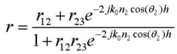
where r12 and r23 are the Fresnel interface complex reflection coefficients for the respective interfaces. For most values of N3, we can find a real index N2 so that
the magnitudes of r12 and r23 are equal (for the lossless case at normal incidence, that index is simply the geometric mean of N1 and N3). However, since r23 is complex
(for an absorbing substrate), the phase of r23 will not be zero (or 180°). Therefore the phase delay introduced by the (summed) return reflections in the layer will not cancel for the usual "quarter wavelength normal to layer" condition.
However the layer thickness can simply be reduced to compensate for the phase angle of r23 and this will provide an ideal zero reflectivity condition. Furthermore, if the substrate loss
is small enough, it is a very good approximation to take the layer index N2, for any θ, as that for the lossless case at that θ, and the layer thickness simply lowered to get the correct phase delay.
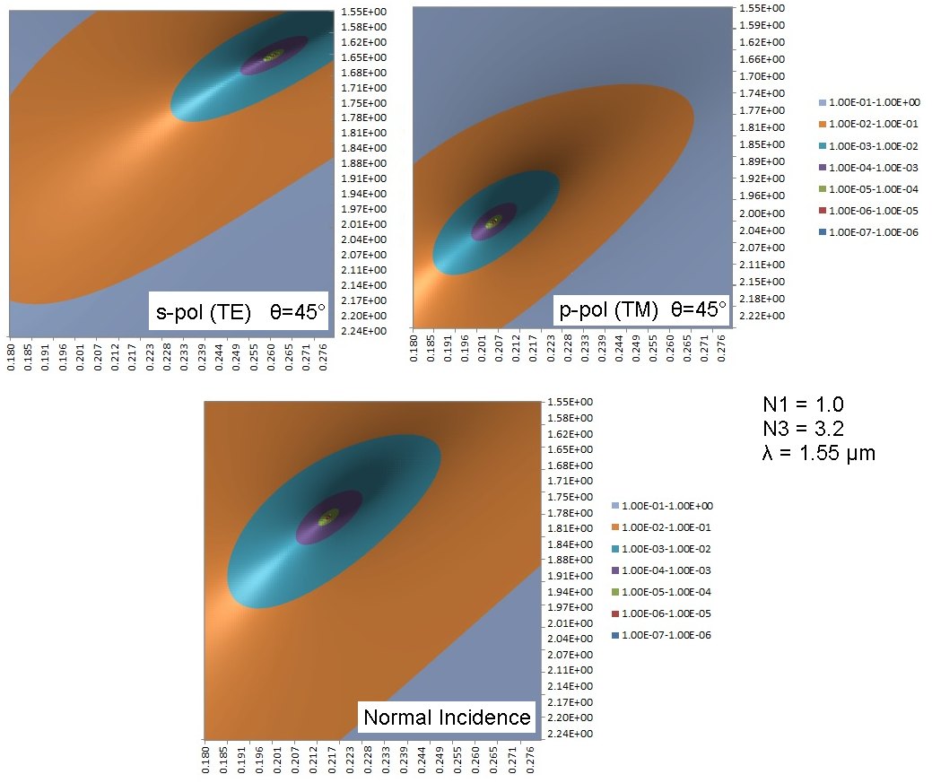
Comparison of S and P Polarization with Angle Of Incidence
The contour plots below show power reflectance contours versus N2 (vertical) and T2 (horizontal) for θ=45° for the S and P polarizations corresponding to the default parameters
in the zero reflectance AR lossless calculator above. Also included is the contour plot for the normal incidence case, demonstrating the considerable change of optimum layer index and thickness for a
perfect antireflection single-layer coating for a fairly large incident angle of 45°. The contour plots also provide some perspective in terms of process control required for layer refractive index and thickness. Note that the contour value
scale is logarithmic. The zero-reflectance bulls-eye point is clearly evident.
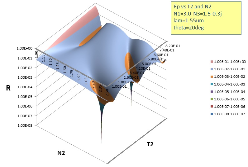
The contour plot below shows a reflectance map with a lossy substrate for the P pol. case with three AR coating solutions shown. Two of the solutions are for the same
N2=2.21 value between N1 and N3 and are separated in thickness by half an optical thickness normal to the layer. The other solution is N2 = 1.16, lower than both N1 and N3 as discussed below:
AR Coating Lossless Equations
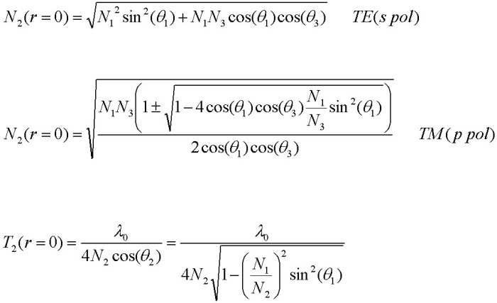
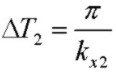
where consecutive zeros for a given N2 differ in thickness by:

The P polarized case has two different AR coating solutions N2p when θ >0. The first N2 solution (+) always has a value between N1 and N3.
The second solution (-) has a value that is less than both N1 and N3 if the incident angle is less than the Brewster angle for the N1/N3 interface, and has
a value between N1 and N3 if θ is greater the Brewster angle.
AR Coating On Lossy Substrate Equations
For multilayer coating calculations, particularly with lossy media, synthesis is usually performed numerically. However for single layer coatings, it is possible to obtain exact
analytical closed-form solutions for AR coatings which are not too complicated and may be used effectively in simple programs on calculators and mobile devices.
In addition, closed-form solutions provide accurate benchmark results for comparison with fully numeric approaches when reduced to single layer cases.
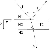
Assume that the incident medium N1 and the AR coating layer N2 are lossless but medium N3 = (N3_re + jN3_im) may be lossy with N3_im <=0. θ1 is the real angle of incidence.
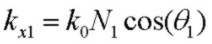
With the XZ being the plane of incidence and X being normal to the layer, the general form of Snell's law is:

and the propogation constant along the interfaces and normal components in the layers are:
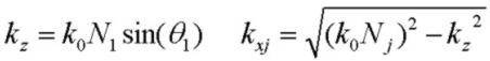
so that:


where N3 and therefore θ3 and kx3 are in general all complex.
S Polarization Case (TE):
In analogy with the completely lossless case above, for given wavelength, angle of incidence, N1 and complex N3, the AR coating parameters kx2, N2 and thickness T2 are obtained by
(a) equating the magnitude of interface Fresnel reflection from the top r12 and bottom r23 interfaces and solving for a real and positive N2 value and
(b) using this value of N2 to determine T2 by requiring a net phase shift in the layer of 180*deg;. Since N3 is complex, the phase angle of r23 will not in general be 0 or 180°.
The solution is:


For a given solution N2 (or kx2) at a specific angle of incidence, as in the lossless case, there are consecutive AR coating thicknesses differing by
1/2 optical wavelength in thickness "normal" to the layer, i.e. :
but the actual thickness values T2 are shifted from the lossless values for a lossy N3 due to the phase shift of r23.
A real solution for kx2 and therefore N2 will exist if:

For normal incidence, the solution for both the S and P polarization cases reduces to:
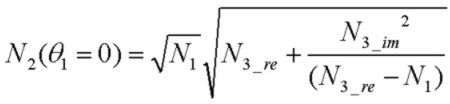
and a real N2 solution exists if:

P Polarization Case (TM):
The P polarization case is slightly more complicated, but can be solved in exactly the same manner with simple substitutions noting that we can replace kxj with ηj where:

η1 and η3 values are given. η2 is determined first and then N2
is obtained from the quadratic in N2 (this usually provides two valid AR coating solutions with different N2 values) and then kx2 and finally T2. A contour
plot showing three AR coating solutions is shown above. Two of the solutions (as in the case of S pol) have the same N2 value but thickness
difference of half an optical wavelength normal to the layer. The other solution is discussed above in the lossless section. The solutions are:


A real solution for kx2 and therefore N2 will exist if:

If the conditions for a REAL AR solution for N2 are not satisfied (either S or P case), an AR solution may exist, but with a complex (lossy) N2 value.
In this more complicated situation with attenuation in the layer, numerical computation can be used.
Reference:
- Optical Properties of Thin Solid Films, O. S. Heavens, 1965, Dover
- Thin-Film Optical Filters, H. A. Macleod, 2nd Edn., 1986, Adam Hilger Ltd., Bristol pp 28-29
- Principles Of Optics, M. Born and E. Wolf, 5th Edn. 1975, Pergamon Press, pp. 61-63
- Electromagnetic Theory, J. Stratton, 1941, McGraw Hill
- Field Theory of Guided Waves, R. E. Collin, 1991, IEEE Press
- Fields and Waves in Communication Electronics, S. Ramo, J. Whinnery, T. Van Duzer, 1984, J. Wiley & Sons