
MIG: Mobile Input for Guitar
A Preamp to match electric guitar to line-in
Jan 22, 2012
Summary:
 This article describes a circuit which enables any standard electric guitar to be interfaced with any audio "line-in" system.
The MIG (Mobile Input for Guitar) consumes very little power and is:
This article describes a circuit which enables any standard electric guitar to be interfaced with any audio "line-in" system.
The MIG (Mobile Input for Guitar) consumes very little power and is:
- a simple design
- easy to use
- inexpensive
- portable
- versatile
Background
Electric guitar amplifiers have specific design requirements which are considerably different from those of a typical home stereo amplifier.
Hi-Fi audio systems are designed to have a flat frequency response over the audio range of 20 Hz to 20 kHz. Additionally, home
audio systems feature very low distortion, low noise and wide dynamic range. Furthermore the hi-fi audio speaker system is a key part of
the hi-fi audio chain. The overall goal of the hi-fi system is to reproduce as accurately as possible, the audio signals entering the
amplifier/speaker chain from traditional electronic sources such as tape decks, tuners and CD players which generally represent
low output impedances to the amplifier input.
By comparison, the characteristics of the typical electric guitar pickup and the electromagnetic inductive effect of the
vibrating steel guitar strings largely determine
the requirements of the guitar amplifier, including the input stage impedance, frequency response and output speakers used, whether the amp is a
tube or solid-state design.
This is further complicated by the sound modifications introduced by distortion in the amplifier, which is often
introduced in guitar amplifier design as a desirable effect. The benefits of these types of sound "coloration" are highly subjective
and different manufacturers approach guitar amplifier design in many different ways. To some extent, a great
deal of guitar amplifier design is based on electronic circuit modification and listening trials with some black-magic mixed in.
It is not the intention of this article to address sound modifications or distortion but to focus on the very specific aspect
of matching an electric guitar to the audio "line-in" or auxilary connection of the hi-fi stereo amplifier and other similar inputs.
Although there is a large variety of different types of electric guitar pickup,
the most common types (single-coil and double-coil humbucking) are characterized by high inductance and matching
moderately high series resistance, determined by the number of windings and gauge-size of the pickup wire. Typical values
are 2 - 6 Henry inductance and series winding resistance of 4 - 10 kohm with higher output ("hotter") pickups having higher
values.
 Simply put, a typical electric guitar pickup is a high-impedance inductive transducer.
Although the pickup is a relatively complicated component in terms of an accurate electrical equivalent circuit, the
essential performance can be reduced to a simplified model of a pure voltage source in series with an inductance and series resistance, shunted by the self-capacitance
of the coil. Thus, the pickup can be characterized as a self-resonant LCR equivalent circuit with self-resonant frequencies typically in
the range of 5 - 10 kHz. The actual values of the LCR equivalent components depend on the details of the pickup construction including wire gauge,
wire spacing and winding geometry, magnet material and strength etc. The measured parameters for a Fender Jaguar neck pickup are shown to
the right with a resonant frequency of 7.1 kHz (see section below for details of measurement procedure). Note that any extra shunt capacitance, including wiring capacitance in the guitar and patch-chord capacitance
will directly modify the actual resonant frequency. For example, the Jaguar has a measured internal wiring capacitance of 70 pF which will increase total
shunt capacitance and lower the effective resonant frequency to 5.8 kHz. Furthermore, with the addition of a 6' patch chord
with typical capacitance of 200 - 300 pF, the actual resonant frequency will be shifted down further to 3.8 kHz changing the tone significantly with less "brightness".
Simply put, a typical electric guitar pickup is a high-impedance inductive transducer.
Although the pickup is a relatively complicated component in terms of an accurate electrical equivalent circuit, the
essential performance can be reduced to a simplified model of a pure voltage source in series with an inductance and series resistance, shunted by the self-capacitance
of the coil. Thus, the pickup can be characterized as a self-resonant LCR equivalent circuit with self-resonant frequencies typically in
the range of 5 - 10 kHz. The actual values of the LCR equivalent components depend on the details of the pickup construction including wire gauge,
wire spacing and winding geometry, magnet material and strength etc. The measured parameters for a Fender Jaguar neck pickup are shown to
the right with a resonant frequency of 7.1 kHz (see section below for details of measurement procedure). Note that any extra shunt capacitance, including wiring capacitance in the guitar and patch-chord capacitance
will directly modify the actual resonant frequency. For example, the Jaguar has a measured internal wiring capacitance of 70 pF which will increase total
shunt capacitance and lower the effective resonant frequency to 5.8 kHz. Furthermore, with the addition of a 6' patch chord
with typical capacitance of 200 - 300 pF, the actual resonant frequency will be shifted down further to 3.8 kHz changing the tone significantly with less "brightness".
Typical signal
levels, for moderate level string picking/strumming are roughly 400 mV peak at frequencies of hundreds of Hertz.
Due to the high inductance of most pickups, the electric guitar amplifier must have a high-impedance in order to ensure good
overall high frequency response of the pickup-amplifier combination. Roughly speaking this requires an amplifier input impedance
of at least several-hundred kohms in the audible region.
Almost all commercial electric-guitar amplifiers (tube and solid-state) satisfy this requirement.
By comparison, most commercial stereo amplifier systems have Tape/CD/Auxiliary inputs with considerably lower standard impedances of about 47 kohm
or lower which are designed to match the output circuits of tape decks, tuners and CD players.
This is not a good "match" to the typical guitar pickup and will "load down" the pickup signal.
If an electric guitar is directly connected to this type of input, significant high-frequency attenuation will result, leading
to a "dull" bassy tone with a noticeable lack of brightness.
 In order to use a typical electric guitar with a home stereo system, the choices are:
- use any effect pedal (distortion, chorus etc..) which usually has a high-input impedance and low output impedance
- if you have an older stereo system with a "phono input" jack (for a turnbable), use a simple
passive-network compensating cable
C:\istarweb\www\phoneaxe\phoneaxe.html
- build a simple low-gain preamplifier with a high input impedance to act as a buffer between the guitar and the
ubiquitous "line-in" connection
This article describes the MIG : a simple, portable, inexpensive single-power supply, single op-amp preamplifier solution
which allows electric-guitars, and acoustic guitars with pickups, to be used with any standard "line-in" connection.
Examples include typical home stereo systems, computer sound cards, TV systems with "audio in/Auxilary" jacks, newer automobiles with "Aux/line-in" jacks.
Many small portable sound systems also feature a "line-in" jack.
The Circuit:
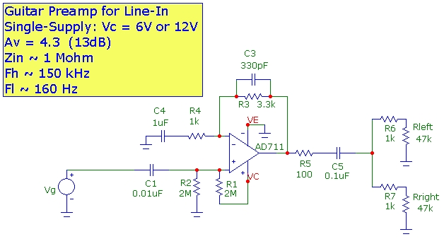
The MIG circuit described here is a single op-amp circuit, using a single power-supply configuration in the non-inverting amplifier configuration.
The circuit shown below is designed with a mid-band voltage gain of 4.3 and an input impedance of about 1 Mohm which will be adequate
for almost all electric-guitar/stereo-amplifier/line-in combinations. A FET-input op-amp is best since this type has very high input impedance and also
very low input bias current which reduces any DC output offset problems. The Analog Devices BiFET AD711 has a gain-bandwidth product of 3 MHz and a slew-rate of 20V/us which provides excellent
bandwidth and transient response for this type of audio application where low to moderate voltage gain is required. The National LF411 has similar performance with somewhat lower slew-rate.
Quiescent current draw is a low 2.4mA for the AD711 and 1.6 mA for the LF411 at Vc=6V. The OPA134PA provides a somewhat higher output voltage before clipping but
with slightly higher current draw of 4mA.
The National TLV27701IP has even lower supply
current of about 1 mA but in this case Vc must be no greater than 6V. However, the supply voltage can be as low as 2.5V which means that even
partially depleted AA batteries can be used. In all cases, a power source consisting of 4xAA rechargeable NiMH batteries is a good choice.
Referring to the schematic diagram below, the input is capacitively coupled via C1 and the op-amp output is biased
at Vc/2 using the R1/R2 2 Mohm voltage divider at the non-inverting input since the DC gain is unity. The low-frequency cutoff is determined by the feedback network of
C4 and R4 (160 Hz cutoff) which provides good low-frequency response over the guitar frequency range and lowers low-frequency noise amplification.
The high-frequency 3dB cutoff frequency is determined by the R3 C3 combination at 150 kHz. R6 and R7 provide output short circuit protection
and a mono fan-out for the two stereo channels. Rleft and Rright represent typical load impedances of the stereo amplifier.
A low frequency cutoff down to 20 Hz can be achieved by modifying the circuit and replacing each of C1, C4 and C5 with values 10x higher.
However, with most stereo systems, this will result in too strong a bass response using normal hi-fi speakers and the typical electric guitar.
The MIG can also be used as a low distortion general purpose high-fi preamplifier using these modified capacitor values.
For Av=10 (20 dB) change R3 to 9kohm with an f3db of 150 kHz. For Av=100 (40 dB) change R3 to 100 kohm
with a resultant f3db of 30 kHz.
The dual oscilloscope trace below shows a typical guitar signal (barred G-chord) at a typical strumming level (Channel 1) for a Fender Jaguar guitar with
guitar volume set at maximum. The peak signal level is about 400 mV. The channel 2 is the op-amp output after the
output decoupling capacitor C5 showing a gain of 4.3.

A bread boarded version of the MIG circuit is shown below with input at right side and output at left side.
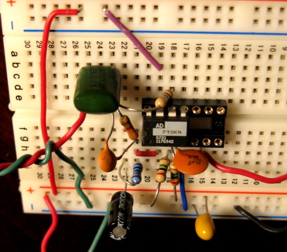
Simply mounting a small bread board in a shielded aluminum box, as shown below, with a standard 1/4" phone jack for the guitar input, and
two RCA phono jacks and a stereo 1/8" mini-jack for output connections to the line-in device will provide a versatile low noise hum-free configuration.
This is useful for experimental work to see the effects of circuit modification. However, for best performance and greatest mechanical
stability, the circuit should be finalized to a printed circuit-board. In a shielded enclosure and without a guitar
connected, the noise of this circuit is dominated by the thermal noise of the 1 Mohm input resistance. The output
noise level is about 100 microvolt RMS over a bandwidth of 20 kHz providing very good signal to noise ratio.
When powered at Vc=6V using 4xAA batteries with 2000 mAHr capacity, several hundred hours of service can be expected.

The single-supply voltage can be as low as 6V (5V for the OPA134PA). In this case, the maximum input signal before op-amp output clipping occurs
is about Vin_max ~ 400 mV peak, a typical signal level at moderate guitar playing level. The output signal swing is centered at Vc/2.
If a "hotter" pickup is used, then a simple input voltage divider attenuation can be used, or somewhat higher supply voltages can
raise the clipping limit as shown below (for Vc=9V, Vin_max ~ 700 mV peak and for Vc=12V, Vin_max ~ 1V peak). Alternately,
the gain of the circuit can be lowered by increasing R4 providing more input headroom. (For example, with R4=7.6k, R3=3.3k, Av=1.43 or 3.1dB,
and Vin_max increases to about 1.5V peak.)
The channel 2 traces
below display the voltage signal before the output decoupling capacitor, showing the output signal with the quiescent DC output level at Vc/2.

Input (channel 1) and output (channel 2) 1 kHz signal at Vc = 6V

Input (channel 1) and output (channel 2) 1 kHz signal at Vc = 9V

Input (channel 1) and output (channel 2) 1 kHz signal at Vc=12V
Simulated Frequency Response:
It is instructive to initially use a simple model for a typical electric guitar pickup and amplifier combination.
The guitar pickup transducer system is represented as an ideal induced voltage source Vpick in series with an inductor Lc and resistance Rc shunted by the sum of capacitances Cc,
Cj and Ccable as discussed above. (any input capacitance at the amplifier can be simply added to Ccable for this simulation).
Representative values for the Fender Jaguar guitar pickup are used.
It is easy to simulate the expected overall frequency response of this circuit.
Most electric guitars have tone and volume controls which shape the frequency response. For simplicity
these controls are not included in the simulation since they don't change the overall results.
Guitars are typically connected to the amplifier using a coaxial patch chord of length about 6 feet. An additional shunting
capacitance Ccable of 200 pF is therefore included.
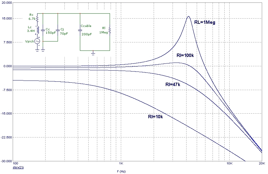
The simplified passive circuit shown below in the inset models the MIG simply as
an input impedance Rl representing the effective load on the guitar-cable combination.
The simulation below shows the effects of changing only the preamplifier load impedance Rl. The marked "loading"
by the amplifier for input impedances below 100 kohm at higher frequency is evident. The response peaking at several
kHz is caused by the resonant LC circuit comprising the pickup inductance and all shunt capacitances. Since the op-amp bandwidth
will be very high, it does not limit the overall bandwidth of the response, but merely serves to provide a moderate
midband gain value as well as to define the input impedance value, represented by Rl in the circuit.
The simulation below for the same simplified passive circuit demonstrates the effect of varying the capacitance between guitar and preamplifier.
The benefits of lowering the capacitance between
the guitar pickup and amplifier input are clearly evident. The resonant peaking is at high frequency providing a brighter sound.
This demonstrates the advantage of mounting a preamplifier at or inside the guitar. In this case,
the preamplifier circuit also provides a "line driver" capability and isolates the guitar patch chord capacitance from
the guitar pickup:

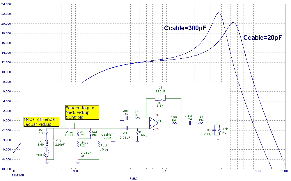
Finally, the entire response of the combined pickup, guitar, coupling capacitances and the op-amp circuit is shown below for cable capacitances of 20 and 300 pF.
The response shown is the transfer function from pickup induced voltage source Vpick to the final output at RL of 47kohm. With a minimal 20pF coupling capacitance, the
f3db high frequency is 8.5kHz with a resonant peak at 5.3kHz. With a typical cable coupling capacitance of 300pF, the f3db high frequency is 5.8kHz with a resonant
peak at 3.8kHz.
The tone and volume control circuits for the Fender Jaguar are also shown here, with settings at maximum and with the "mid-cut" filter shorted. The controls in this case
have minimal effect on the overall response. The overall low-frequency response is determined by the op-amp low-pass filter Ri and Ci as discussed above and can
be extended to lower frequency by increasing Ci.
The spectral curves below show how the resonant peak shifts to lower frequency as extra capacitance is added. The spectrum is that of the G (3rd) string
plucked, after the initial "attack". The fundamental frequency (~ 196 Hz) and higher even and odd harmonics are clearly visible:

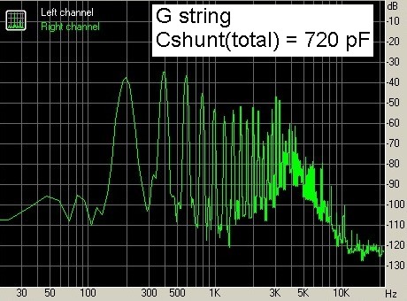
Sample MP3 file: G string plucked twice with 720pF load and twice with 250 pF load
Examples:
The MIG connected to the Aux input of a 2010 Mazda 3:


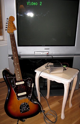
The MIG connected to the Audio In of a TV set:
Measurement Details:
A Micronta Multimeter (RS 22-194), a
Syscomp Electronic Design Ltd.
DSO-101 dual channel 3 MHz USB oscilloscope and WGM-101 100kHz range function generator were used. These meters provide more than enough capability for
any type of audio measurement and are very convenient for use with a laptop computer. They are used below to determine circuit impedances, providing similar results to measurements using an impedance bridge.
First the multimeter was used (with all guitar controls set at maximum) to measure the pickup DC resistance of 6.7kohm.
Next, a simple measurement circuit, with a 100kohm series resistor was configured as shown below to measure capacitance and resonant frequency:
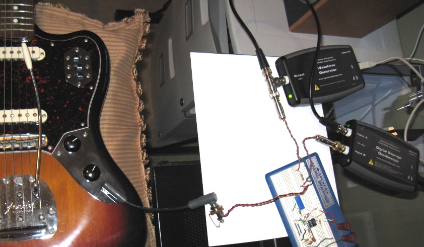
First the overall measurement capacitance of
interconnet wires and connectors (without the guitar connected and without the scope and function generator connected) was measured with the multimeter to be 60 pF.
Next, a direct voltage divider amplitude measurement with the scope and function generator at 30kHz was made and fitted to a simple series RC model yielding 80pF which
is 20pF higher than the multimeter measurement due to the 20pF input capacitance of the oscilloscope.
Next, the guitar was plugged into the test circuit, BUT WITH THE PICKUP SWITCHED OUT OF THE CIRCUIT. All the guitar controls were set at maximum.
Again a voltage divider amplitude measrement and a simple RC model yielded a total shunt capacitance of 150pF.
Therefore the internal guitar wiring/shunt capacitance is (150 - 80pF) = 70pF.
Next, the Jaguar neck pickup was switched in. The frequency was swept and the resonant frequency determined to be 5.2kHz (maximum amplitude at resonance).
The oscilloscope traces below show "below resonance" (3 kHz) with inductive reactance dominating the phase shift, and "above resonance" at 8 kHz with capacitative reactance
dominating the phase shift. Channel 1 (red) is the voltage at the function generator and channel 2 (blue) is the voltage after the 100kohm resistor (voltage across all
shunt capacitances and the pickup):
Below resonance (inductive):

Resonance:

Above resonance (capacitative):

The measured resonant frequency along with the measured amplitudes of the response below and above resonance were then compared to a
simple model of the pickup described above and including the shunt capacitances and the 100kohm measurement voltage-divider series resistor.
The extra capacitance added by the pickup was determined to be 150 pF and the inductance was deteremined to be 3.4H.
References
- Measuring Impedance and Frequency Response of Guitar Pickups, Syscomp Electronic Design Ltd. App. Note, 2011
- Guitar Electronics for Musicians, Donald Brosnac, 1983, AMSCO Publications
- Audio IC Op_Amp Applications, 3rd Edn. Walter G. Jung, 1986, SAMS pp.102, 114
- Electric Guitar Amplifier Handbook, 4th Edn. Jack Darr, 1977, SAMS
- National Semiconductor Audio/Radio Handbook, 1980, National Semiconductor
- The Tube Amp Book, 4.1th Edn, Aspen Pittman, 1995, Groove Tubes