
Speed of Light with an IR LED
M. Gallant Nov 11, 2010
The speed of light has been measured many different ways using many ingenious methods. The following note describes
a method which is conceptually easy to understand and fairly easy to implement. The technique is the simple
time-of-flight optical pulse delay method using a short (20 nanosecond) intense infrared LED optical pulse, a high speed
photodiode and preamplifier and an oscilloscope with a bandwidth between 50 - 100 MHz.
The Measurement
The light from the LED passes through a beamsplitter (BS) close to the source. The reflected light from the beamsplitter (path L0) is focused
onto the photodiode (Pd). The light that passes throught the beamsplitter (path L1 = L1a + L1b) travels a much longer path to a mirror and is reflected
and focused using a different lens onto the same photodiode. If the path difference (L1 - L0) is long enough and the LED optical pulse
is short enough, the optical pulses focused onto the photodiode will not overlap in time. A measurement of the path difference (L1 - L0) and the
measured time difference of the electrical pulses from the photodiode receiver circuit allow for an easy determination of the free space
speed of light. With careful length measurements, a modest accuracy of about 1% is achievable:

The LED
A high-speed and intense infrared LED is most convenient for the optical measurement. High speed means that shorter optical
pulses can be created facilitating shorter delay paths. High intensity means that optical alignment and focusing is easier.
A Vishay 870 nm IR LED (TSFF5210) was chosen with a bandwidth of 25 MHz with tr/tf ~ 15ns. A high speed high current
avalanche transistor (2n2369a) pulser circuit was used to drive the LED with 25 ns 600 mA peak current pulses with a duty cycle of 0.2%
which is within the specifications for this LED.
The schematic diagram and compact circuit board for the IR LED pulse source is shown below:


The Photodiode Receiver
A Vishay BPV10 high speed Si pin photodiode with a bandwidth of 200 MHz was used to detect the light pulses. The photodiode was
reverse biased at 15V to increase speed and lower capacitance.
An AD8001 op amp preamplifier in a noninverting configuration with a gain of 35 (31 dB) and BW of 50 MHz was use to amplify the photodiode signal.
The input termination resistance of 50 ohm combined with this gain is equivalent to a transimpedance of 1.75 kohm.


The Optics
It is important to optimize the optical collection since an LED source is not well collimated. Using good lens focusing and collimation is
essentially "noiseless" gain. The noise level of higher-gain preamplifiers will reduce the ability to detect weak signals particularly over long
optical delay paths. In the current setup the LED output was collimated with a lense of f = 300 mm and diam=4" as shown below. The light from path L0
was focused onto the photodiode with a f=75mm lens and light from path L1 was focused with a f=125mm lens of comparable thickness
as shown below:


The Results
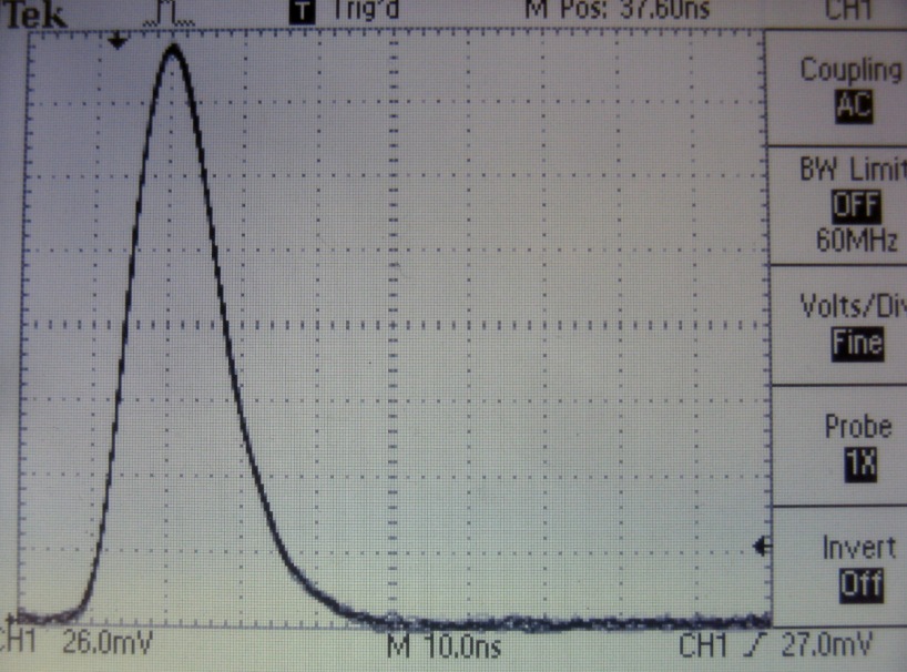
The optical pulse from the beamsplitter path (L0) is shown below (the L1 path was optically blocked). The pulse width is approximately 30ns in duration.
The pulse fall time is about 12 ns, limited by the LED response time and consistent with its 25 MHz bandwidth. It was verified that the photodiode and preamplifier
circuit combination operated well within the linearity limits :
To ensure that the delayed optical pulse did not overlap in time with the "tail" of the beamsplit pulse, a delay time of at least 40ns was required and therefore a
delay time of about 60 ns was chosen (corresponding roughly to a 60 ft path difference).
The image below shows both the beamsplit and delayed pulses, showing a very clean separation of the two optical pulses. The beamsplitter was adjusted
to ensure that both received optical pulses were of comparable amplitude to minimize any possible source of intensity dependence of pulse shape. As can
be seen, the two pulses are virtually identical. Although the oscilloscope has a bandwidth of 60 MHz corresponding to tr~tf = 6ns, it is possible to measure the time delay
to an accuracy of about 1ns because the pulse shape and intensity for the two pulses is the same:

The peak signal voltage amplitude from the output of the photodiode amplifier is given by:
Vp(mv) = Pp(mW) x R(mA/mW) x RL x Av x 0.5
where Pp is the peak optical power received by the photodiode active area, R(mW/mA) is the photodiode responsivity at the LED wavelength of 870 nm
which is 0.55 mA/mW, RL is the 50 ohm photodiode load resistance at the input of the op amp, Av is the noninverting op amp voltage gain
of 35 and the factor of 0.5 accounts for the voltage divider between the op amp output series resistance and the input termination resistance of the oscilloscope.
Using this expression, and with a measured Vp of about 200 mV, the optical power received at the detector is about 0.4 mW.
The image below shows the measured time delay of the two pulses:

The Measurements
The time delay between the pulse peaks was measured on a 60 MHz Tek TDS210 oscilloscope to be:
62ns +/- 1ns
The path lengths were carefully measured as:
     L0 = 38 1/4  +/- 1/4 "
     L1 = 767  +/- 1"
    (L1 - L0) = 728 3/4 +/- 2"  = 1851 cm
The dominant source of measurement error is the time measurement at about 1.6%.
Therefore the value of the speed of light in air is determined to be:
     c = 1851cm / 62ns
     c ~= (2.99 +/- 0.05) x 10^10  cm/sec.
in agreement with the accepted value of c.