
A Simple High Performance Headset Amplifier
May 15, 2011
This note describes a very simple stereo headset amplifier providing superb audio results. The circuit described is suitable for driving
low-power headsets or earbuds to sufficient listening levels from line-level signals of about 2Vrms. While many commercial inexpensive earbuds have poor
audio characteristics (based on my testing), some provide astounding audio quality.
[Note: Larger headphones requiring high-drive capability would require modification of this circuit with a
transistor push-pull output stage, or paralleled op-amp outputs as discussed at the end of this article.]
The circuit uses a high-performance National dual LM4562NA op-amp in the inverting unity-gain configuration (for best linearity). This op-amp
is specifically designed for very-high performance audio amplifier applications. The LM4562NA has a GBW of 50 MHz, a slew-rate of
20V/us and exceptionally low THD specifications. Other popular dual op-amps such as the NE5532 will provide similar performance.
The output drive capability of 26 mA/channel is easily sufficient to drive small low-power
headsets and earbuds with the typical 2Vrms audio-output levels from modern CD and DVD players. An input impedance of 10 kohm provides
good buffering for any line-out source. The 100 pF shunt capacitance across the
feedback resistor rolls the response off with a 160 kHz -3dB bandwidth. The breadboarded version of the circuit below was used for testing
and optimization purposes. At least two sets of small headphones can be driven simultaneously.
The values of output series resistors shown in the schematic diagram below were selected based on my personal listening level taste for two different small 32 ohm headsets with considerably different output headphone efficiencies.
As a guideline, with a +/- 6DVC power supply, the LM4562NA can deliver up
or 3.5 Vpeak (35 mA peak) into a 100 ohm load or 4.2 Vpeak (23 mA) into a 180 ohm load without clipping.
(Note that some other dual op-amps which specify 50 mA peak current, will deliver lower peak current outputs at +/- 6V supplies.).
Sufficient output voltage swing headroom is required to prevent clipping for high input signal levels.
The LM4562 output can swing within ~ 2 V of Vcc/Vee. To allow operation with +/- 4.5 dual supplies or with op-amps
that have lower output swing capability, the Rf resistor can be lowered to 6.8kohm which provides ~ 3dB attenuation in the feedback loop, resulting
in somewhat lower output level, but without clipping with input levels of 2Vrms.
With a total IC quiescent current draw of 10 mA, this circuit can be easily powered with a home-made dual +/- 6V DC battery.
RMAA testing of this amplifier with a Rl = 150 ohm and a series 32 ohm headset confirm what careful listening reveals (as shown by
the summary results at the bottom). Outstanding audio performance.
Schematic diagram of headset amplifier circuit:

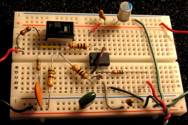
Breadboarded circuit (with the Cf shunt capacitors removed for clarity):

4"x3"x5" aluminum enclosure for the headset amplifier. The 4 right-lower RCA phono-jacks are inputs and testing outputs.
Left and upper-right jacks are headphone outputs. The power-in and power switch are on opposite side of box.

Portable +/- 6V (or +12V) power supply containing 8 AA cells


Thermal Considerations
It is important to understand the thermal limitations in using a typical dual DIP op-amp for applications where significant current will be delivered to a load.
As an example of a simple thermal calculation, consider the LM4562NA op-amp in the circuit shown above. The dual supply voltage is +/- 6VDC.
Let's assume a total load resistance of 180 ohm (150 ohm output series resistance with 30 ohm headphone load), and with an op-amp output voltage of 2.5 Vpeak.
Assuming that the final stage of the op-amp internal circuit is a typical push-pull configuration, we can apply the usual device power-dissipation equations,
for given power-supply rails and output peak voltage swing to obtain: Pd = 71 mW (for the total of the two amplifier circuits, since this is a dual op-amp)
Pq = 10mA X 12V = 120 mW (since the Iq is 5 mA per channel, and +/- 6V supplies)
Pt = Pd + Pq = 191 mW (since the total device dissipation is the sum of quiescent and signal power dissipation)
With a typical thermal resistance Rja of 90 C/mW for a plastic DIP, a maximum ambient temperature of 50C and a conservative Tjmax of 110C, the
maximum allowable op-amp power dissipation (total) will be 670 mW. Therefore the actual operating conditions above are well within the thermal limits of this
device.
Extending the Output Current Drive Capability
An easy way to extend the current output capability of an op-amp is to simply parallel the outputs of a dual op-amp which facilitates driving less efficient
or larger headphones with impedances of ~ 50 ohm. (This approach has the advantage of simplicity compared to a discrete transistor push-pull output booster, but of course will have less
drive capability.) One method of achieving this uses an inverter as the input
with the output connected to a follower with outputs summed through small resistors. This can roughly double the output current capability of an opamp.
The circuit below shows the configuration appropriate to the inverting unity-gain configuration. Adding extra paralleled-amps is also possible for even
greater output :

In this case the input impedance in the passband is 5.6kohm. The 10 ohm output resistors equalize current contribution from each opamp. Of course, for
a stereo configuration, this would require two dual opamps, one for each channel. The output damper network R1, C1 might help reduce instability effects
for some op-amps and was not required for the LM4562NA.
A typical protoboard layout is shown below for the LM4562NA dual op-amp:
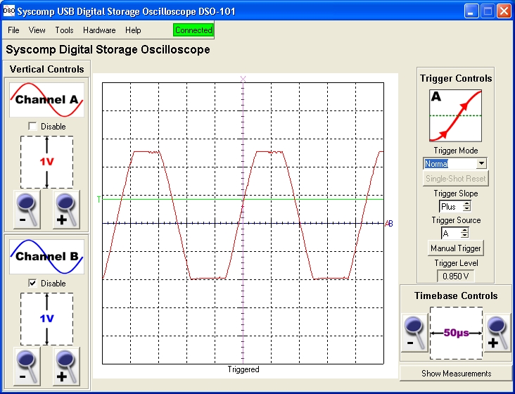
To demonstrate the improved current drive capability for this type of circuit, the output voltage at 4.5 kHz of an LM4562NA opamp is shown below for an input level of 4.0V peak with +/- 6V supplies.
The output shows a (maximum) clean output into 51 ohms of 3.5 Vp or 120 mW. This is a peak output current of 69mA, roughly double the capability of a single LM4562 channel.
This output capability extends to at least 100 kHz.
A thermal calculation shows that the device power dissipation is well within the maximum dissipation limit under these circuit conditions and with +/- 6V supplies. Note that the
device dissipation depends strongly on the supply voltages. Therefore, for higher supply rails such as +/-12V, the dissipation would be significantly
higher and thermally marginal for this type of op-amp and for the output signal levels of interest here:

For comparison, if the follower output is disconnected so that only one of the op-amp channels is driving the output load, the current limit for a single channel of the LM4562NA is exceeded (at this level of input voltage).
With this 51 ohm load, a maximum output unclipped voltage of only 1.9V peak is possible corresponding to 37 mA maximum drive current or 35 mW power delivered to the 51 ohm load:
Comparison with other popular op-amps indicates that the LM4562NA performs very well with no signs of instability or "frizzies" under the above test conditions.
The distortion and noise performance of the doubled-op-amp circuit under these test conditions are excellent and similar to that discussed above.