
1 Amp Pulsed LED
Mar 06, 2013
 Common LEDs have typical DC forward current ratings of 20mA. For many types of visible and infrared LEDs it is possible to apply much higher current pulses provided
that the pulse width in time and repetition rate is low enough. In some but not all cases, information on high-current pulsing is provided in the datasheets. The duty cycle (DS) of the pulse is the product of the pulse width times the repetition rate and indicates
the average power (and therefore heating) delivered to the LED. With pulse widths of a few µseconds or less and DS of less than 1%, it is possible for many types
of LEDs to drive peak pulse currents of 1 Amp through an LED providing very intense short pulses of light which can be used for various applications.
An example is provided below using a common high-radiance white LED.
Common LEDs have typical DC forward current ratings of 20mA. For many types of visible and infrared LEDs it is possible to apply much higher current pulses provided
that the pulse width in time and repetition rate is low enough. In some but not all cases, information on high-current pulsing is provided in the datasheets. The duty cycle (DS) of the pulse is the product of the pulse width times the repetition rate and indicates
the average power (and therefore heating) delivered to the LED. With pulse widths of a few µseconds or less and DS of less than 1%, it is possible for many types
of LEDs to drive peak pulse currents of 1 Amp through an LED providing very intense short pulses of light which can be used for various applications.
An example is provided below using a common high-radiance white LED.
A Transistor Avalanche Pulse Circuit
A free-running
pulse-generation circuit
using a single transistor in avalanche mode can be used to drive brief very high current pulses through an LED. The example below
shows a typical circuit using the 2N2369a transistor which can be used to generate very short < 500ps electrical pulses for a variety of applications.
In the example presented here, the collector capacitor C1 is fairly high to provide pulses of several 100 ns width to reasonably match typical response times of visible LEDs.
The high-voltage source Vs charges the collector capacitor C1 through a high resistance R1 relatively slowly until the transistor breakdown voltage of 70-90V is exceeded. Then the transistor conducts strongly in avalanche
breakdown mode and C1 discharges through Re (22 ohm) and the LED (typically a few ohms dynamic resistance). The DS of the pulse is therefore approximately Re/R1.
The 1 ohm resistor is used to measure the peak pulse current. The 51 ohm shunt resistor Rs provides a low impedance path for the LED recovery following the avalanche breakdown.
(WARNING: in operating an LED at high pulsed currents beyond the device specification, it is wise to start with low pulse currents by increasing Re and observing carefully for
any deterioration with time in the light output):
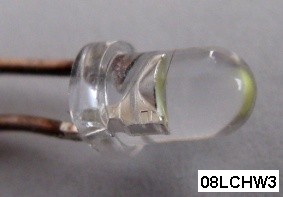
The LED shown below is a 08LCHW3 InGaN white LED with a 2MHz small-signal bandwidth. This LED is spec'd for a maximum DC current of 30 mA and a maximum pulsed current
of 100mA (at 100µsec pulse width and 1% DS). The peak pulse current as measured by the voltage across Rm is about 1.1Amp, more than 10 times higher than the actual rated pulse spec.
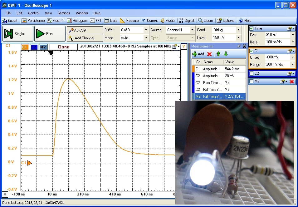
The oscilloscope traces below show the light output pulse using a high-speed photodiode circuit. The pulse period is 230 µsec and the pulse width is ~ 400ns
corresponding to a low DS of 0.2%. The peak optical output power was measured to be ~ 30x that of the LED operating at 20mA DC.
After several hours of operation, the LED showed no sign of degradation in peak optical output.

Variable High-Current LED Driver
The circuit below uses paralleled power transistors in emitter-follower configuration to acheve controlled variable pulsed drive current levels up to ~ 2Apeak with fall times ~ 20 ns.
It is intended to be used with a pulse-generator having variable pulse amplitude up to 10V and with tr/tf ~ 10ns such as the Syscomp Design WGM-201.
The 50MHz MJE182 power transistors are rated at 1.5W (without heat sinking) with peak pulsed collector current spec'd at 6A.
The total LED current is shared between the collector currents of the four power transistors which shortens the response time.
Since the emitter-follower response time depends on the circuit resistance looking "back from the base of the transistors", a high slew-rate 70 MHz op-amp buffer with slew-rate of 1000 V/µs is used to
ensure very low effective input resistance and sufficiently fast response time. The 10 Ω resistors in the transistor base circuit can be removed to achieve very fast pulse fall times but with more undershoot.
With a peak LED current of 1A at 1% duty-cucle, the required drive voltage at the input to the op-amp buffer is Vo=2.0Vpeak. The βDC of the transistors at 1 A is ~ 125 so with
4 transistors in parallel, the effective resistance of the paralleled-transistors is ~ βDC*Re/4 = 150 Ω. Therefore the buffer op-amp must source 14mA for 1A LED current or 28mA for 2A LED current,
well within the drive capability of most high-speed op-amps.
At 1A peak LED current, each transistor and emitter resistor 4.7Ω 1/2W carries (Vo-0.8)/4.7 or 250mApeak current or 1.2Vpeak or 300mWpeak.
To ensure sufficient voltage compliance to drive white LEDs (which have typical forward voltages of ~ 10Vpeak at 1A), the supply voltage should be 12 - 15VDC. To ensure safe thermal operation of the transistors,
the maximum duty cycle (for 1Apeak) should be less than ~ 10%. Since the intent is to drive LEDs with 1-2% duty cycle at 1 Amp, the power transistors without heat-sinking
will operate in a safe region.


The scope traces below shows the drive current (V_Re voltage across the emitter resistor) and the photoresponse V_opt for a typical high-radiance red LED driven at
500 mA peak and 2% DS. The drive pulse fall time is less than 15ns. This LED has an optical fall time of 155ns corresponding to a large signal bandwidth of ~ 2MHz :

How Intense?
The human eye has a response time of ~ 1 ms and therefore will integrate the luminous energy and perceive only an average luminous intensity for the very short pulses
above.
However it is interesting to calculate the peak luminous intensity of this pulsed LED as follows:
The luminous flux Iv of the LED at 20mA current from the spec. sheet is 4000 mcd = 4 cd = 4 lumen/sr.
At 1.1 Amp pulsed LED current, the measured photocurrent is about 30X higher than the DC photocurrent at 20mA.
Assuming the same emitted LED spectral distribution under pulsed conditions, the peak luminous intensity at 1.1 Amp is therefore Iv = 120 cd = 120 lumen/sr.
How "bright" is this? A typical 100W incandescent light bulb has a total luminous flux of Φv ~ 1630 lumens (RCA EO Handbook). Since this
flux is emitted roughly uniformly into a full sphere of 4π sr, this corresponds to a peak luminous intensity of Iv of ~ 130 lumen/sr.
Therefore the peak intensity of the pulsed white LED is comparable to the CW intensity of a 100W incandescent light bulb.
However since the DS of the pulsed LED is only 0.2%, the average luminous intensity, which is the perceived brightness of the LED, is much lower.
As another benchmark, we can ask how close to the human eye must this pulsed LED be placed so that the peak illuminance Ev (lumen/m^2) will be the same
as that of the sun at the zenith on a clear day? According to the RCA EO Handbook, the solar illuminance Ev is 1.2E5 lumen/m^2. (In radiant units, for the solar
spectrum this corresponds to ~ 1.3kW/m^2 or 130mW/cm^2).
The illuminance of a source is simply the luminous intensity divided by the distance squared Ev = Iv/R^2. Therefore the
1.1A pulsed white LED must be placed 3 cm or ~ 1" from the human eye to have a peak brightness equal to that of the sun. Again, the average brightness
of the LED will be much lower.
References:
- Light Emitting Diodes, Forest M. Mims, III, 1973, H. Sams, pp. 58-61.
- RCA Electro-Optics Handbook , EOH-11, 1974 pp. 53-57, 76.
- "Triggered 250 Picosecond Rise Time Pulse Generator" in Linear Technology Corp. application note
AN61, Jim Williams, 1994