
LED Frequency Response
Feb19, 2013
This article describes frequency response measurements of common light emitting diodes (LEDs) using the
Digilent Analog Discovery design kit.

LEDs:
The frequency response of LEDs is measured by applying a fixed bias current with a superimposed small signal AC current and the
modulation frequency is scanned. A high-speed photodiode amplifier circuit detects the modulated photocurrent signal. The -3 dB frequency of the amplified photocurrent
signal is a measurement of the "speed" of the LED. The f3db frequency of LEDs can vary over a wide range depending on the intended use from 1 MHz (indicators, status) to over 100 MHz (telecommunications).
The example below shows typical frequency response results for three common LEDs: red, white and high-radiance infrared LEDs.
Measurement Configuration:
LED current modulation was applied using the Discovery W1 waveform generator with the offset voltage used for adjusting the bias current. This affects a very simple
form of "bias-T" functionality and is suitable for the devices measured here where bias current levels are less than 20 mA.
A 50 Ω series resistor was used to monitor bias and AC current modulation levels. The current monitor signal was connected to Discovery scope Ch1. The bias current
level was set at 10mA. The current modulation was set at +/- 4mA. The peak current level (bias + peak modulation) was well below the maximum current specification for the LEDs.
The photodiode with amplifier circuit has a receiver BW of over 60MHz and does not affect the measured frequency response for the LEDs in this study. The photodiode was reverse-biased
at -30V.
The amplified photocurrent signal was connected to Discovery scope Ch2. The Waveforms Bode plot software was
used to acquire the Ch2 optical response relative to the monitored reference photocurrent signal level Ch1.
All connections were kept very short with suitable resistor terminations to minimize any rolloff effects due to shunt capacitive reactance, particularly from 1 to 10 MHz.
Connections were made using the Digilent Discovery BNC adapter unit. A lens with focal length of 1" was used to collect and focus LED light onto the photodiode active area. :


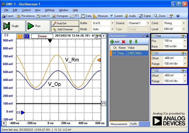
The traces below show the current monitor voltage across Rm (V_Rm) and the photodiode amplifier output voltage V_Op at 2 MHz for the IR LED. The zero optical level at the amplifier
output is indicated by the Y1 line which is the circuit output DC offset voltage. The small signal dynamic resistance of the IR LED at 10mA bias was determined by the ratio of LED modulation
voltage to LED current as ~ 5 Ω:
Results:
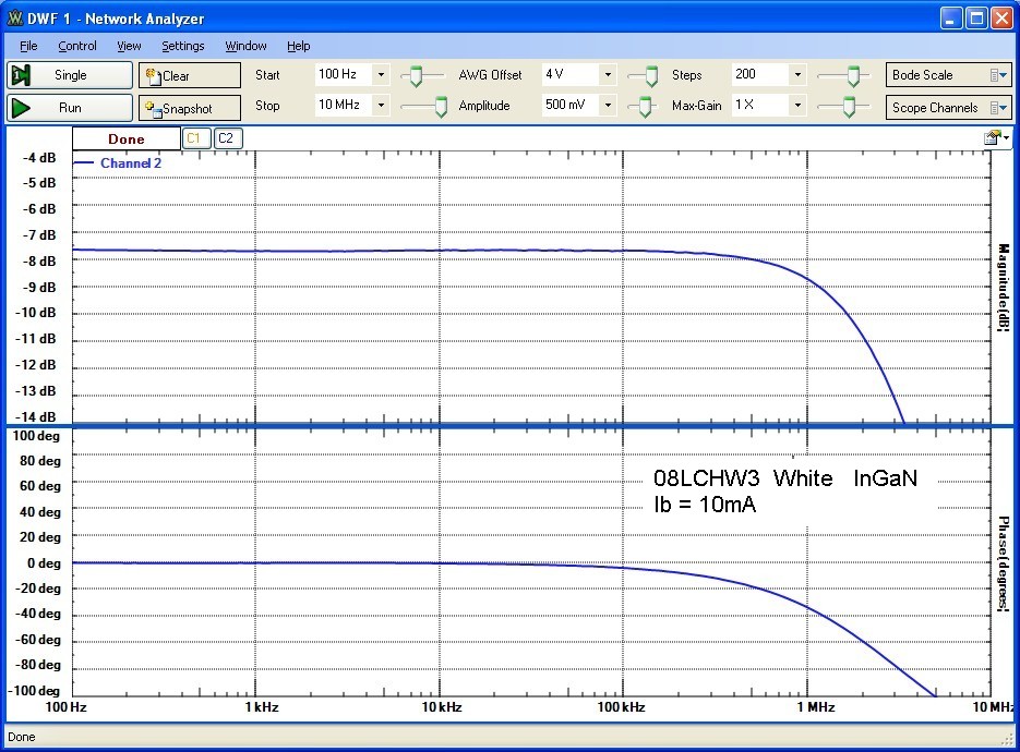
Frequency response results for Vishay TSFF5210 IR, 08LCHR5 red and 08LCHW3 white LEDs are shown below.
The response for the IR LED is flat with a drop of 0.6 dB at 10MHz, consistent with this LED's specified bandwidth of 23MHz.
The red and white LEDs have modulation bandwidths of 9MHz and 2 MHz respectively:


Pulse Response:
Large signal pulsed response measurements (no bias current applied) using the same photodiode amplifier circuit are shown below.
A Syscomp Electronic Design WGM-201 10MHz function generator was used as it provides a
faster rise/fall times than the Discovery W1 generator.
The 10-90% rise/fall times in the transient response are in good agreement
with the f3db small-signal bandwidths shown above with:


A higher resolution transient response for the TSFF5210 IR LED at 20mA is shown below. The 15 - 20 ns rise/fall times are limited by the response time of the 100 MSPS Discovery
scope with slight ringing but are in agreement with the +/- 15ns tr/tf specified by the manufacturer at 100mA:

References:
- Optical Communication Systems , J. Gowar, 1984, Prentice Hall International, pp. 252-259.
- Physics of Semiconductor Devices, S. Sze, 2nd Edn. 1981, pp. 689-700
- Hitachi Optoelectronic Devices Data Book, 1988, p 29